
DFM (design for manufacturing) is a review of a part design before the mould is made. For a compression moulded part it checks draft, wall thickness, undercuts, parting line, material flow and press force, and shows what to change so the part moulds cleanly first time.
DFM analysis before compression mould design
A DFM analysis is the first step of every compression mould design we do. Design for manufacturing means changing the part, where needed, so it moulds well: the right draft, even walls, a sensible parting line and a charge that fills. Our mould flow analysis for SMC and DMC parts studies charge placement and flow fill in 3D, so the mould design starts from a part that will actually fill and release.
What our DFM review checks
Draft analysis
Every face mapped by draft angle, with near-zero and negative areas flagged.
Wall section
Thick and thin areas that cause sink, blisters, long cures or non-fill.
Undercuts and parting line
Whether the part can be a straight-pull tool, and where the parting line and shear edge go.
Charge and flow
Charge weight, placement and how far the compound must flow.
Press tonnage
Projected area times moulding pressure, checked against your press.
Critical features
Engraving, bosses, sealing grooves and inserts that need special care.
Watch: a complete DFM study in 3D
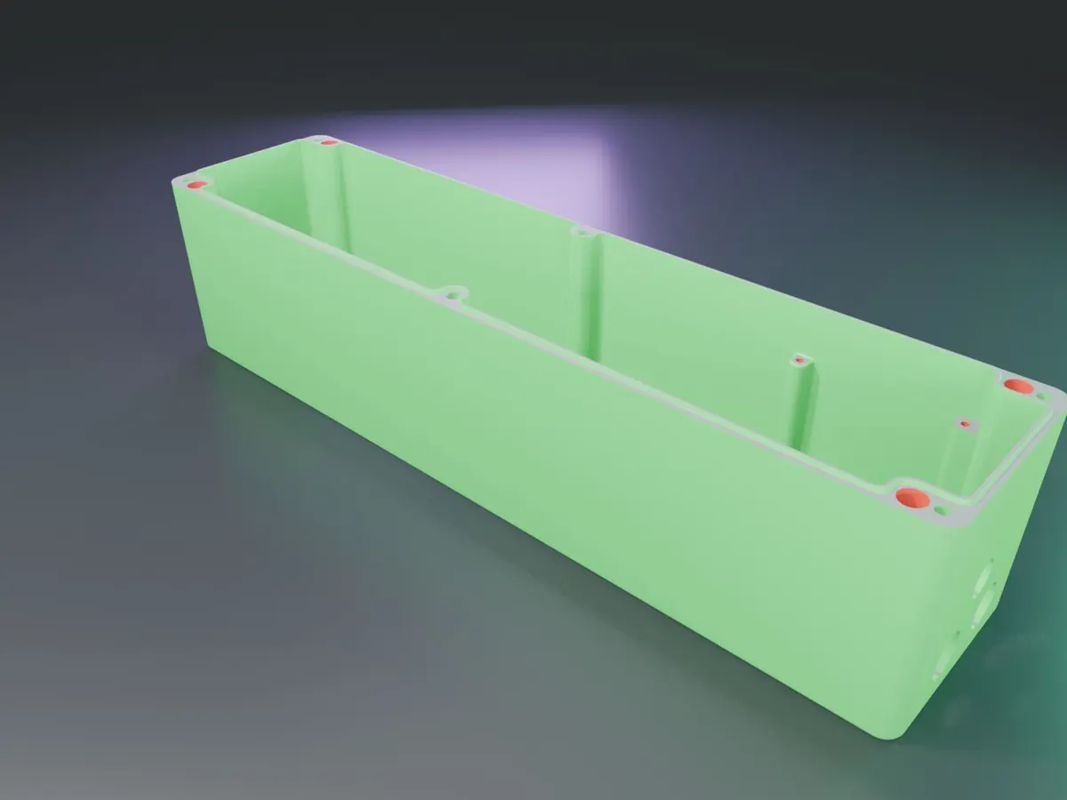
These films show a real DFM and mould feasibility study we made for an SMC electrical enclosure: a base and a lid, both compression moulded in SMC as single-cavity moulds. Each film walks through the part analysis step by step, with narration. It is a customer design, so actual dimensions are not shown.
1. The full assembly: base, lid and 46 components
2. Base: DFM and mould feasibility
Draft and wall-section checks, the cable-entry undercut (moulded straight-pull and machined after moulding, so no slider is needed), insert positions, projected area and press tonnage.
3. Lid: DFM and mould feasibility
Draft and wall section on the lid, ribs and bosses, brass inserts moulded in, the silicone gaskets fitted after painting, and the press force for the lid mould.
Want the same study for your part? Send a 3D model and we will review it free of charge.
Mould design and drawings
Once the DFM is approved we design the mould in 3D: shrink-compensated core and cavity, shear edges, heating layout, ejection, guides and inserts. You receive 2D mould drawings in our standard ISO title-block format, and the design drives CAM for our VMC and EDM electrodes.
Mould type and steel selection
The DFM also sets the mould type (flash, positive or semi-positive), the number of cavities and the steel: hardened H13 or Böhler W302 ESR for cavities, P20 for plates. Read more about compression moulds.
Send your part for a free DFM review
3D model or drawing, material and annual volume. We reply within one working day.