Your drawings stay confidential. We sign NDAs.

+91 9145700873 +91 8625919717 WhatsApp

Main line · Thermoset tooling

Compression Mould Manufacturer in India

Compression moulds for SMC, DMC, BMC, Bakelite, melamine and urea-formaldehyde parts. Every mould is engineered from a DFM review to the first approved part, in our tool room in MIDC Ahilyanagar, Maharashtra.

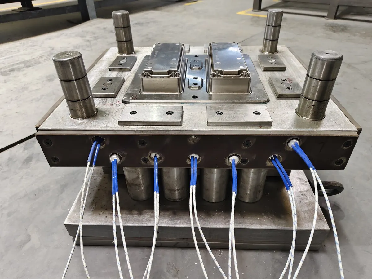
Multi-cavity compression mould inserts with heater cables connected, built by Prime Tools
A multi-cavity compression mould with its heaters connected, in our tool room
Materials
SMC · DMC · BMC · Bakelite · Melamine · UF
Largest mould
850 × 650 × 550 mm
Trialled on presses up to
400 tonnes
Typical lead time
6–8 weeks

What is compression moulding?

Compression moulding is a process where a measured charge of thermoset material is placed in a heated, open mould cavity, the mould is closed under a hydraulic press, and heat and pressure make the material flow into every detail and cure into a rigid, finished part.

It is the standard way to make parts from thermoset compounds such as SMC (sheet moulding compound), DMC and BMC (dough and bulk moulding compound), Bakelite (phenolic), melamine and urea-formaldehyde. Once these materials cure, they cannot be melted again, which is why they hold their shape at high temperatures, resist fire and stay electrically insulating for decades.

That makes compression moulding the backbone of the electrical industry: energy meter boxes, junction and distribution boxes, switchgear insulators, socket and switch housings, and outdoor enclosures that face sun and rain every day. The quality of every one of those parts starts with the mould. As a specialist compression mould manufacturer in India, we build only thermoset tooling, so every mould we make is designed around how these materials flow and cure.

Compression moulding diagram

A compression mould has two halves mounted between the heated platens of a press. The charge is loaded into the lower half (the cavity); the upper half (the force or plunger) closes on it and squeezes the material into shape.

Compression mould open, with the charge loaded in the heated cavity 1 · Open: charge loaded Heated press platen Heated press platen Upper half(force) Guide pillar Plunger Lower half(cavity) Charge Heaters Ejector pins Compression mould closed under heat and pressure, the material filling the cavity and curing 2 · Closed: heat + pressure cure Press force Cured part Shear edge 140–180 °C Ejectors push the part out after cure
Compression moulding diagram: the charge sits in the heated cavity (1), then the press closes the mould and holds it under pressure while the thermoset cures (2). Diagram by Prime Tools.

The compression moulding process, step by step

  1. First, the charge is prepared. SMC sheet is cut and stacked to a set weight; DMC and BMC are weighed as dough; phenolic and melamine powders are often pre-formed into tablets and pre-heated. A correct charge weight is the first defence against short shots and heavy flash.
  2. Next, the charge goes into the heated mould. It is placed in the cavity at the position worked out in the DFM, usually where it covers 40–70% of the projected area for SMC, so the material flows evenly to the edges.
  3. The press closes the mould at a controlled speed. The shear edge traps the material while it flows into ribs, bosses and grooves, and air escapes through the vents.
  4. The part cures under heat and pressure. The thermoset cross-links, and the cure time depends mostly on the thickest wall in the part. That is why uniform wall sections matter at the design stage.
  5. The mould opens and the part is ejected. Ejector pins push the part out square, without distortion.
  6. Finally, the part is deflashed and checked. The thin flash at the parting line is removed and the part is measured against the drawing. A well-made mould keeps that flash small and consistent for years.

Compression moulding materials and typical settings

We build compression moulds for all the main thermoset families. The table gives typical starting ranges; the final settings always come from your material supplier's datasheet and the trial.

Typical compression moulding settings by material
MaterialMould temperatureMoulding pressureTypical partsWhat the mould needs
SMC140–160 °C40–100 kgf/cm²Meter boxes, junction boxes, enclosures, coversHardened, polished steel for glass fibre; tight shear edge
DMC / BMC140–170 °C50–150 kgf/cm²Switchgear parts, insulators, lamp housingsWear-resistant inserts, good venting for detailed ribs
Bakelite (phenolic)150–185 °C150–350 kgf/cm²Wiring devices, handles, electrical basesHigh pressure rating, chrome plating, steady heat
Melamine145–170 °C150–400 kgf/cm²Switch plates, electrical fittings, tablewareMirror finish for gloss, careful gas venting
Urea-formaldehyde135–165 °C150–400 kgf/cm²Sockets, switches, toilet seats, closuresPolished, chrome-plated cavities; precise temperature

SMC moulds: the compression mould we build most

An SMC mould has to handle a glass-fibre compound that is abrasive, flows a long way and cures fast. Our SMC moulds use hardened, polished cavities, a tight vertical shear edge and a charge pattern worked out in the DFM, so the fibres reach every rib and boss without dry spots. We build single and multi-cavity SMC moulds for meter boxes, junction boxes, enclosure bases and lids. See our SMC moulds.

Choosing between thermoset and thermoplastic? Thermosets cure once and keep their strength at high heat, resist fire and electrical tracking, and do not creep under load, which is why they win for electrical and outdoor parts. Thermoplastics re-melt, which suits fast injection moulding but not every electrical job.

What makes a good compression mould

Most compression moulding problems (flash, short fills, blisters, cracks and warpage) are designed in long before the first trial. These are the points our engineers settle before any steel is cut.

Shear edge and flash land

A vertical shear edge with the right clearance traps the material and keeps flash thin. Too loose, and you trim every part; too tight, and the edge galls.

Draft on every wall

Walls, ribs and bosses need draft to release cleanly. We map draft face by face and flag every near-zero area.

Uniform wall sections

Thick sections slow the cure and cause sink and blisters; thin ones risk non-fill. We study the wall map and suggest changes early.

Even heating

Heater layout and thermocouple positions keep the mould surface within a few degrees, so the whole part cures at the same rate.

Venting and ejection

Trapped gas leaves burns and porosity. Vents, ejector positions and stripping are designed around how the material flows.

Steel, hardness and finish

Glass-filled compounds are abrasive. Cavities are made in hardened steel, polished, and hard chromed where the material demands it.

How much press force does a compression mould need?

Press force (tonnes) = projected area (cm²) × moulding pressure (kgf/cm²) ÷ 1000

For example, a cover with a projected area of 300 cm² moulded in SMC at 80 kgf/cm² needs about 300 × 80 ÷ 1000 = 24 tonnes, before a safety margin. We do this check for every part, so the mould suits the press you already have.

Mould steels we use

SteelWhere we use itWhy
H13 (hardened)Cores, cavities and insertsToughness and wear resistance at moulding temperature
Böhler W302 ESRCavities for long runs and abrasive compoundsPremium, electro-slag remelted H13-type steel: cleaner, takes a better polish
P20 (pre-hardened)Plates, holders and low-volume toolsMachinable, stable and cost-effective

Before steel is cut

3D mould feasibility for every part

Before we quote, your part goes through a DFM and feasibility study in 3D. You get a report you can act on, not just a price.

  • Draft and wall-section maps, face by face
  • Parting line, shear edge and undercut check
  • Projected area and press tonnage
  • Charge weight, placement and flow
  • Critical features: engraving, bosses, sealing grooves

Advantages and limitations of compression moulding

Advantages

  • Lower tooling cost than injection or transfer moulds for thermosets
  • Suits large, heavy and thick parts, such as enclosures and covers
  • Little material waste: no sprues or runners
  • Keeps glass fibres long, so parts are strong and stiff
  • Low internal stress and good dimensional stability
  • Parts resist heat and fire and stay electrically insulating

Limitations

  • Longer cycle times than injection moulding, set by cure time
  • Flash at the parting line needs trimming
  • Side cores and deep undercuts make the mould more complex
  • Fine, thin-walled features are harder to fill
  • Needs a well-controlled charge weight on every shot

So when you see the exam question "which is not an advantage of compression moulding?", the usual answer is a short cycle time or flash-free parts. Those are strengths of injection moulding, not compression moulding.

Compression vs transfer vs injection moulding

Compression mouldingTransfer mouldingInjection moulding
How material entersPlaced directly in the open cavityPushed from a pot through runners into a closed mouldInjected by a screw through runners and gates
Best forLarge thermoset parts, SMC and BMC, fibre-filled partsThermoset parts with inserts or fine detailHigh-volume thermoplastic parts
Tooling costLowestMediumHighest
Cycle timeLongerMediumShortest
Material wasteVery lowCull and runnersRunners, unless hot runner
Fibre lengthKept long, strongest partsShortenedShortened most

Products made by compression moulding

Our compression moulds produce parts for enclosure and housing makers across these markets:

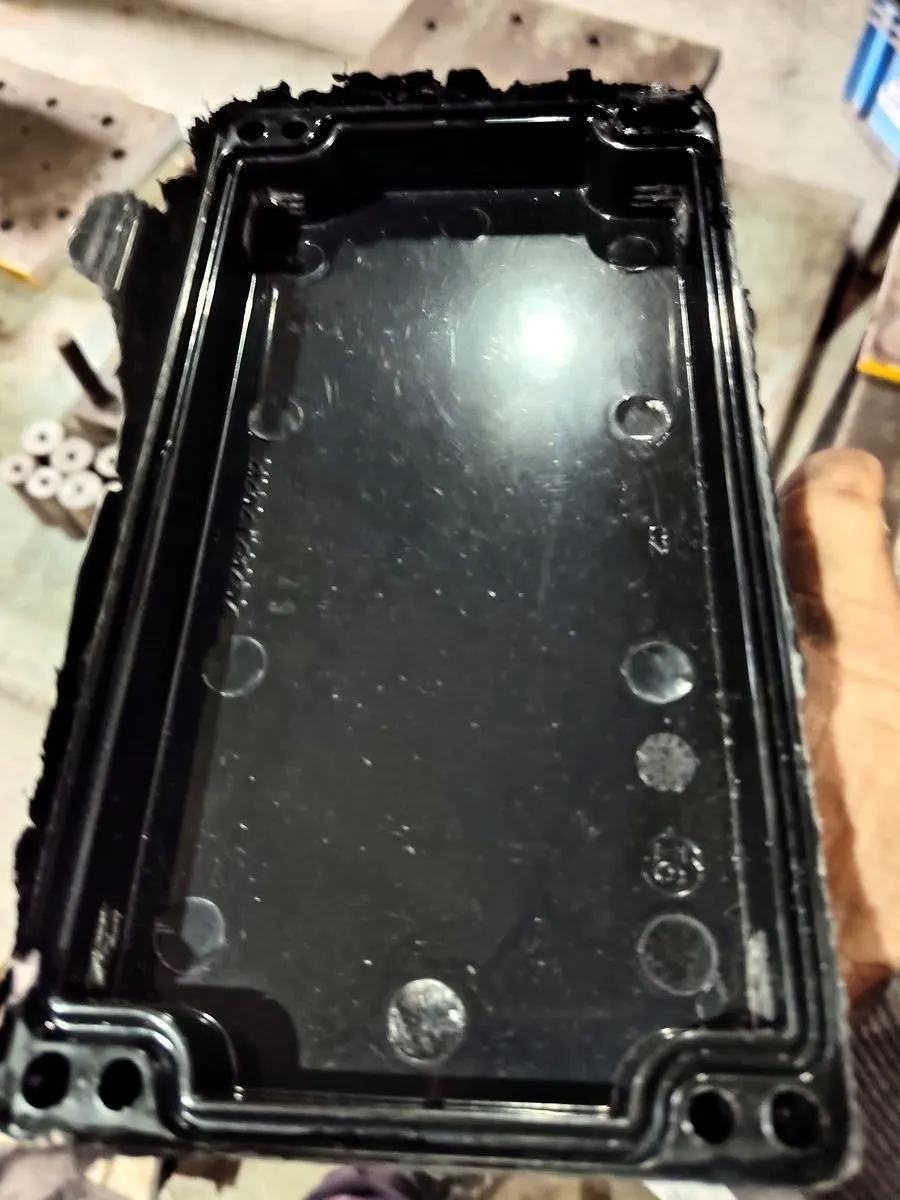
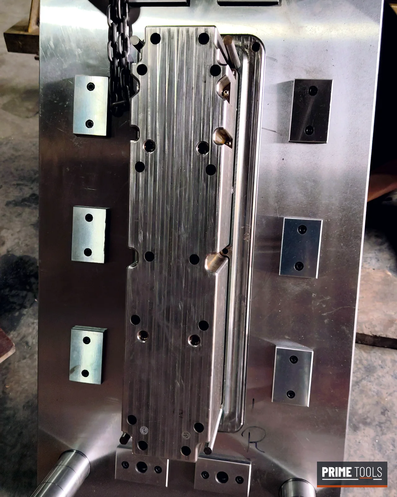
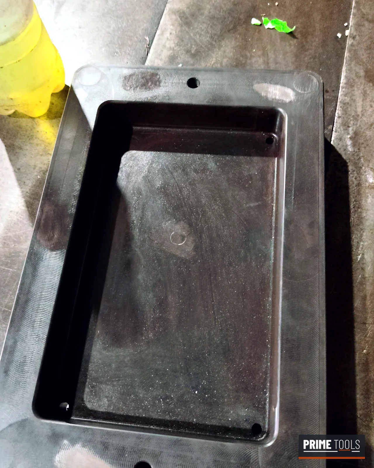
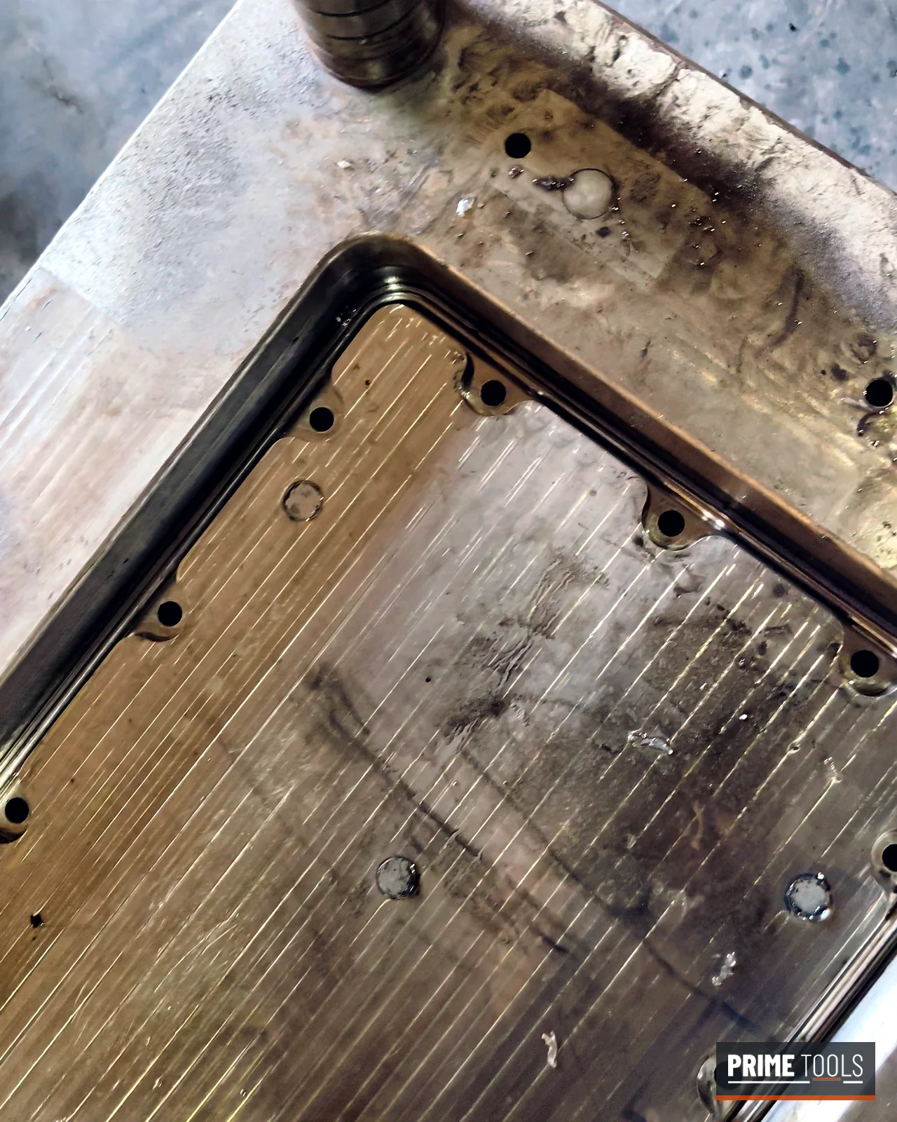
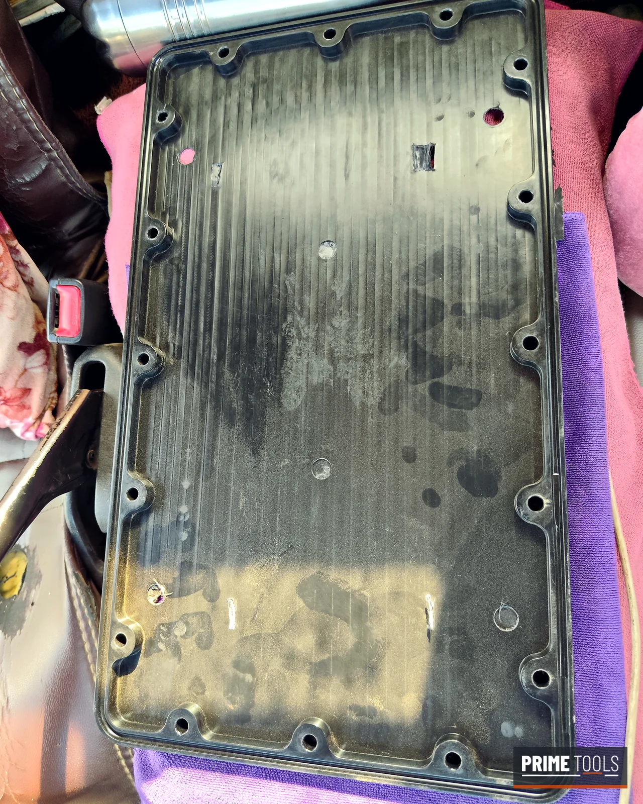
Black SMC enclosure part moulded in a Prime Tools compression mould Core half of a new SMC enclosure base compression mould with support pillars and guide bushes
An SMC enclosure part and the core half of a new SMC mould, both from our tool room.

How we build your compression mould

One team, one tool room: design, machining, fitting and trial under the same roof in MIDC Ahilyanagar.

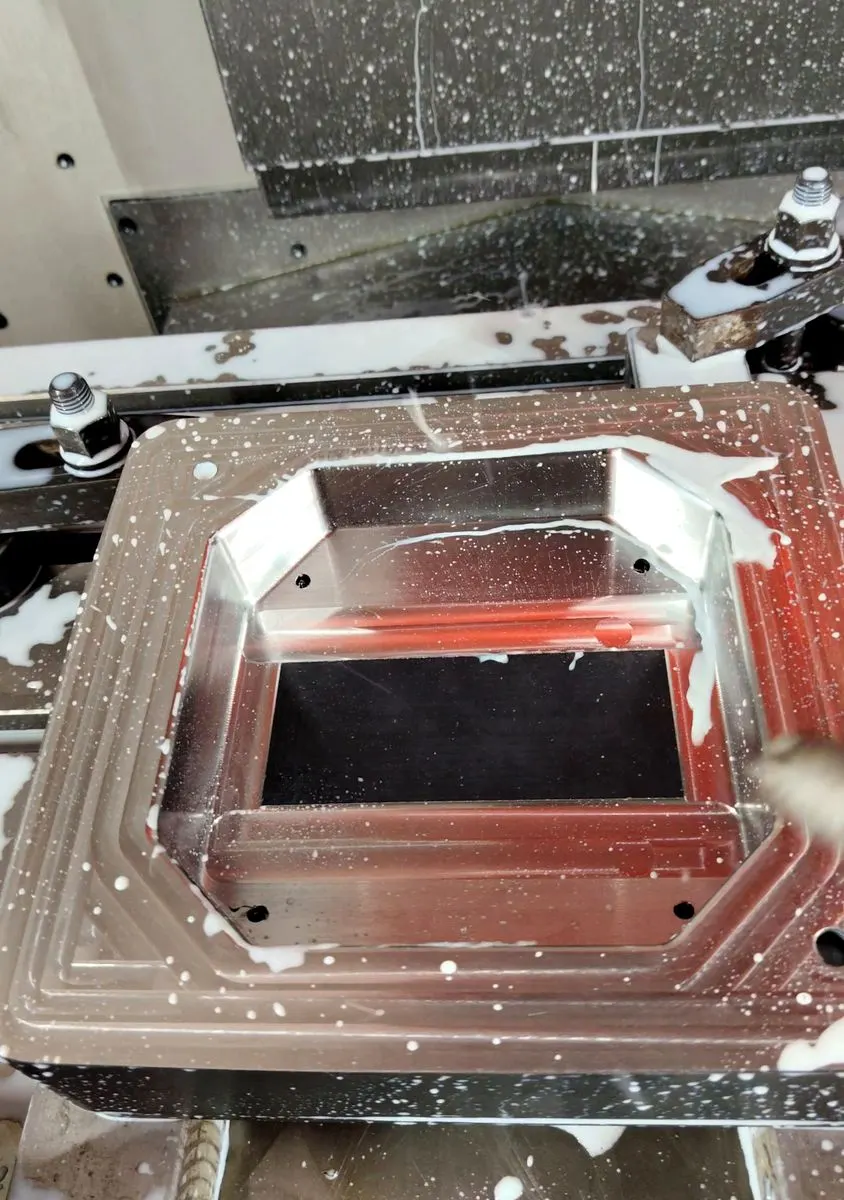
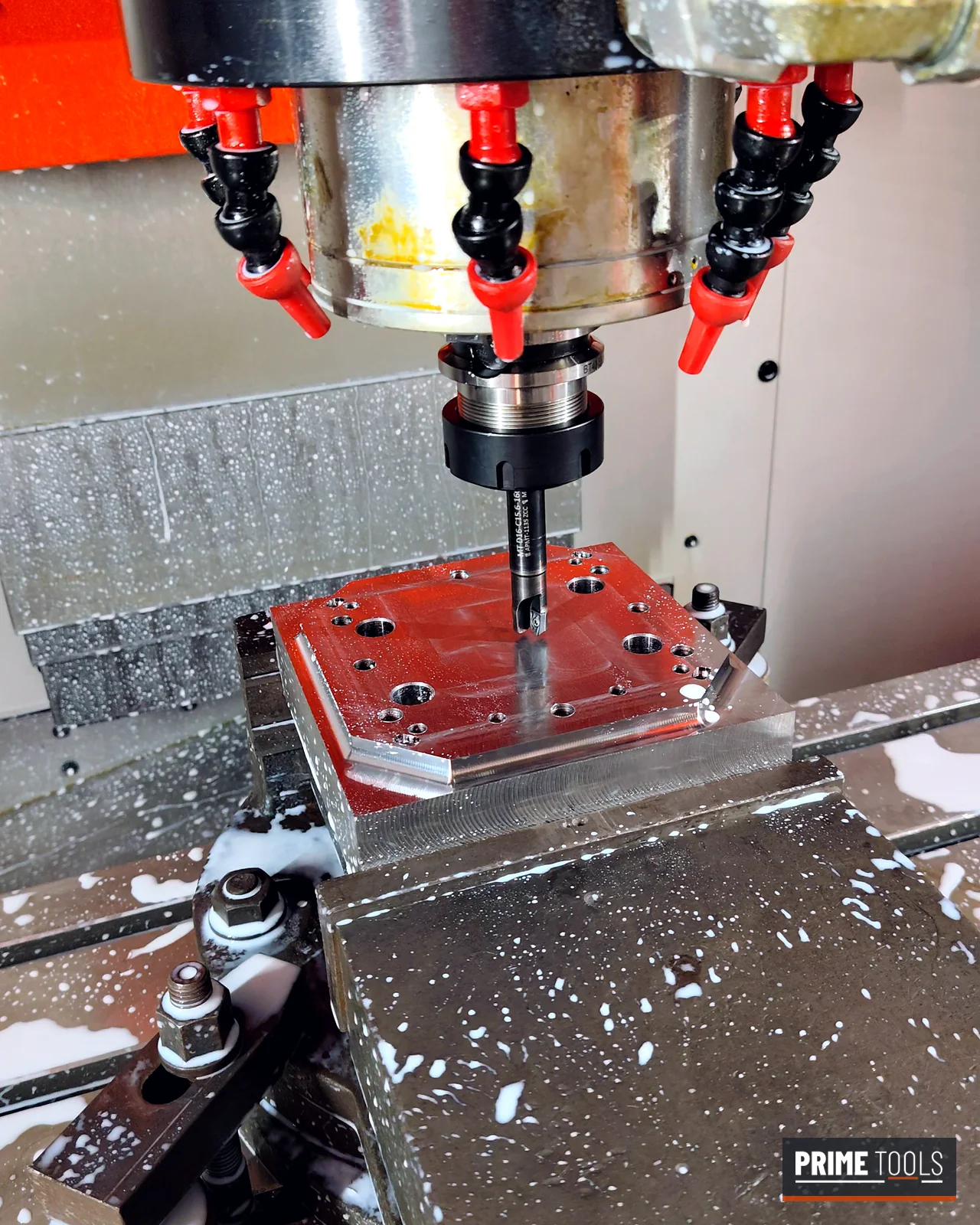
  1. Compression mould cavity being machined on a VMC under coolant

    DFM, design and CAM

    Shrink-compensated 3D design, electrodes and toolpaths, built on the approved DFM.

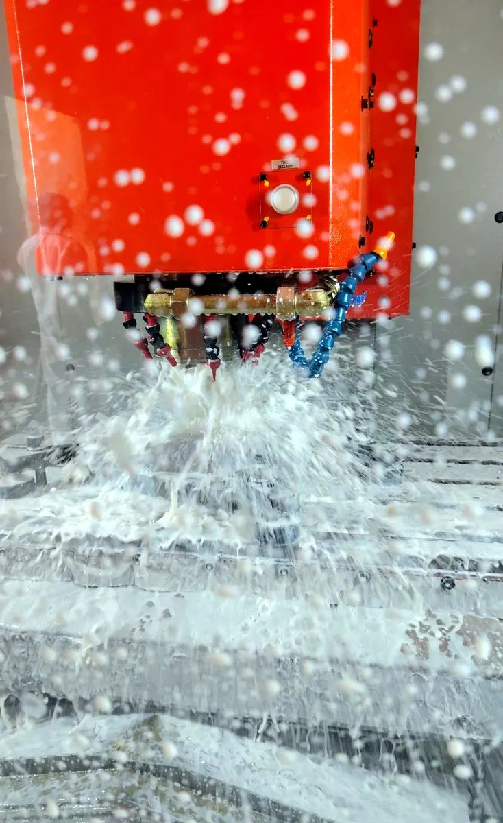
  2. BFW BMV 50 VMC cutting mould steel

    VMC machining

    Roughing and finishing of cores and cavities on our BFW BMV 50.

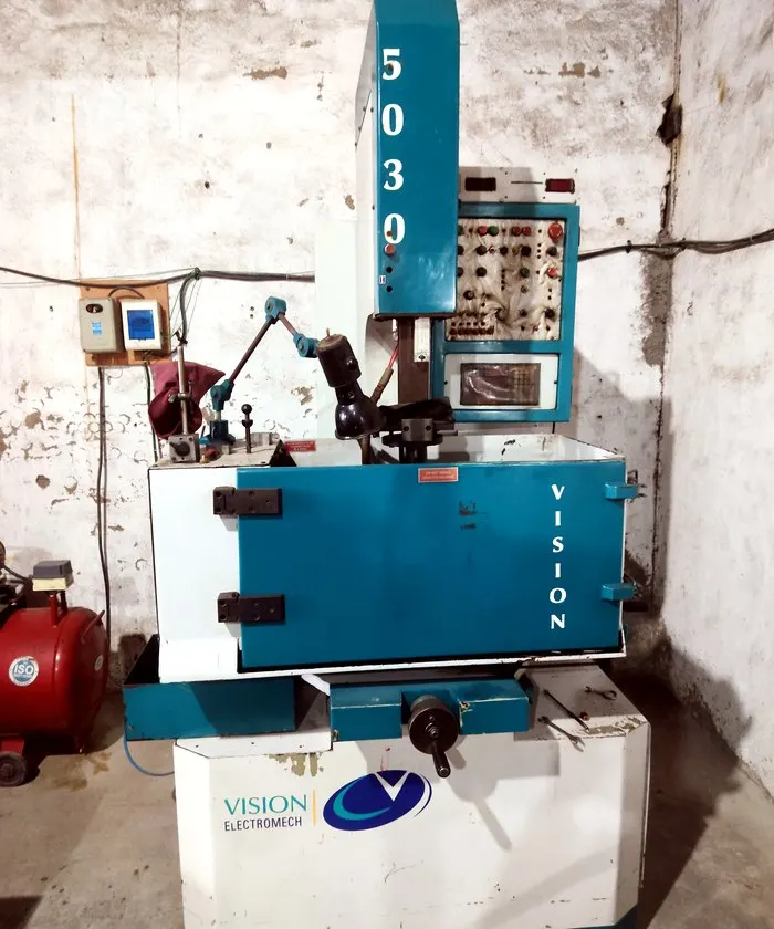
  3. Vision Electro EDM machine used for ribs and engraving

    EDM and grinding

    Ribs, engraving and sharp corners by EDM; plates ground flat and square.

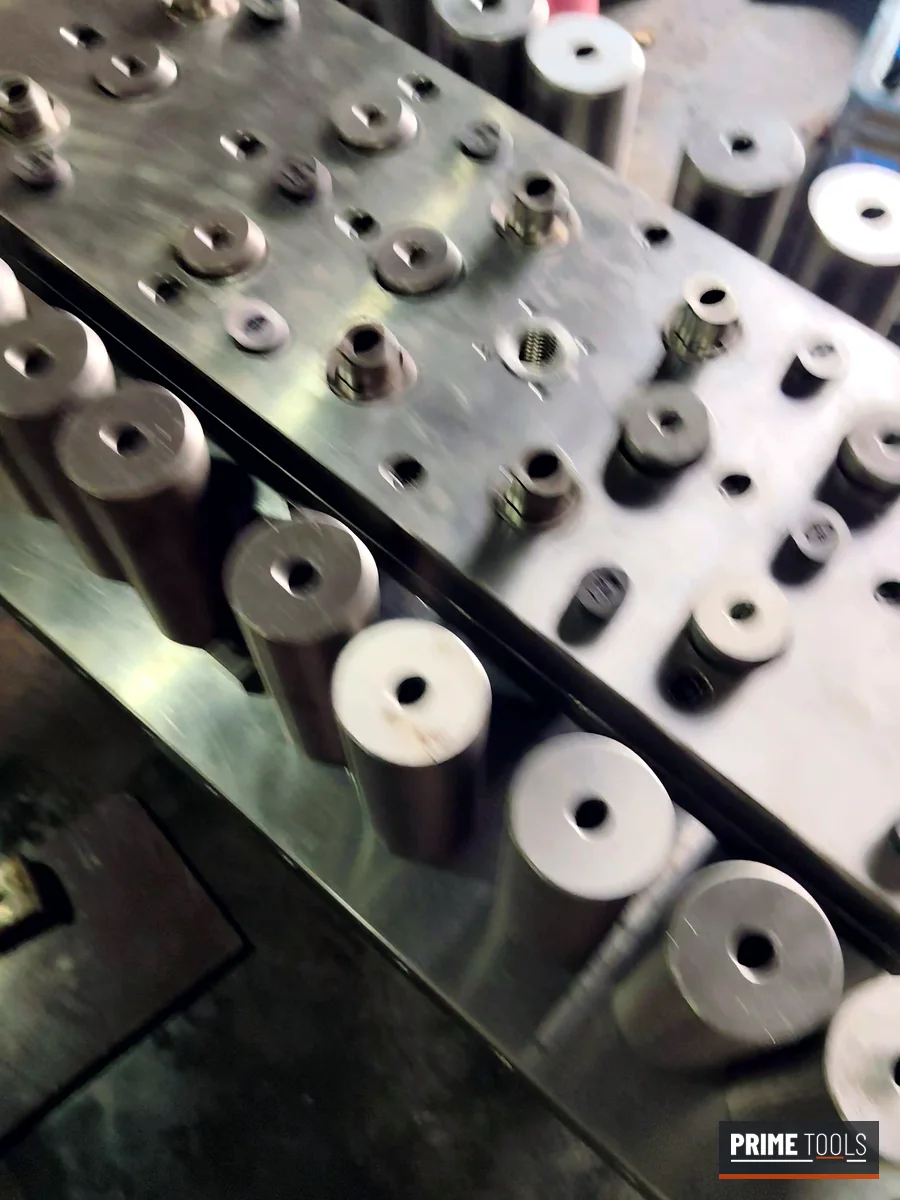
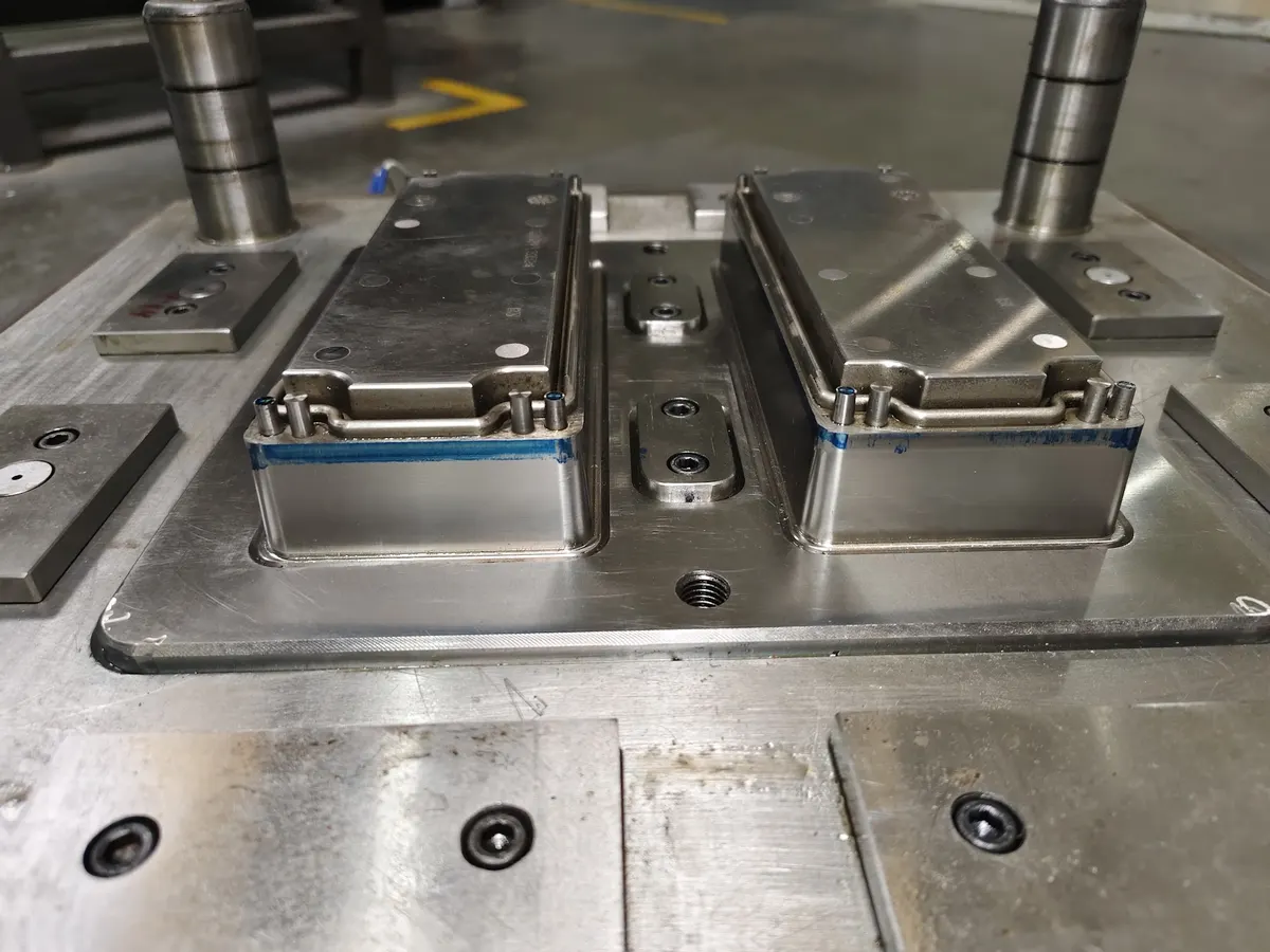
  4. Hardened and polished cavity inserts for a multi-cavity compression mould

    Hardening and polish

    Hardened, polished and chromed where the compound demands it.

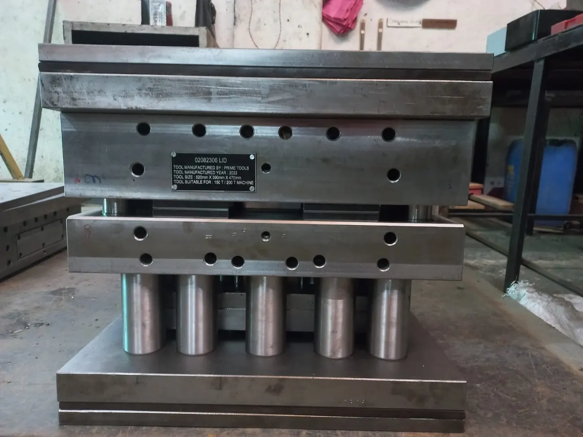
  5. Assembled compression mould with heaters and nameplate

    Fitting and assembly

    Shear edges fitted and blue-matched by hand, heaters wired and tested.

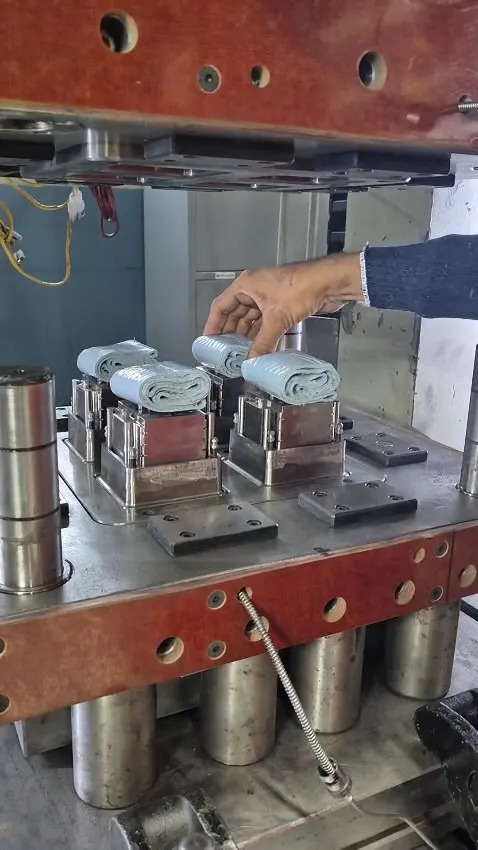
  6. Compression mould on the press at trial with the SMC charge being loaded

    Trial and handover

    Trial on the press, first-off parts for your approval, then packed and delivered.

Compression mould FAQ

What is a compression mould?

A compression mould is a two-part steel tool, mounted between the heated platens of a hydraulic press, that shapes thermoset material. The charge is placed in the lower half (the cavity), the upper half (the force) closes on it, and heat and pressure cure the material into the finished part.

Which materials can you make compression moulds for?

We build compression moulds for SMC, DMC, BMC, Bakelite (phenolic), melamine and urea-formaldehyde. Each material needs a different steel, finish, shear edge and heating layout, which we settle in the DFM review.

How long does it take to make a compression mould?

A typical compression mould takes 6 to 8 weeks from design approval to trial. Large or multi-cavity moulds can take longer; we commit to a date in the quotation and send progress updates.

How much does a compression mould cost?

The price depends on part size, number of cavities, the material, the steel, finish and features such as side cores or engraving. Send your 3D model or drawing with the material and annual volume, and we will send a DFM review and a firm quotation.

What steel do you use for compression moulds?

Cores, cavities and inserts are usually made in hardened H13 or Böhler W302 ESR for abrasive, glass-filled compounds, with P20 for plates and holders. Cavities are polished and hard chromed where the material needs it.

Do you trial the mould before delivery?

Yes. Every mould is trialled and the first-off parts are sent for your approval before handover. Our moulds are trialled on presses up to 400 tonnes.

Can you repair or modify an existing compression mould?

Yes. We repair worn shear edges, re-polish and re-chrome cavities, correct flash and fill problems, and modify moulds for design changes, including moulds made by other tool rooms.

Will you sign an NDA before we share our drawings?

Yes. We sign an NDA on request before you share full details, and we never show customer names or part data in our marketing.

Do you supply compression moulds outside India?

Yes. We quote for buyers outside India and can work to your press details, standards and packing requirements.

Send your part for a free DFM review

  1. Send your part. 3D model or drawing, plus material and annual volume.
  2. Free DFM review. A report on draft, walls, flow, venting and ejection risks.
  3. Quotation. Mould price, steel and a lead time we commit to.
  4. Mould build. Typically 6–8 weeks, with progress updates.
  5. Trial and handover. Trial and first-off parts for your approval.