
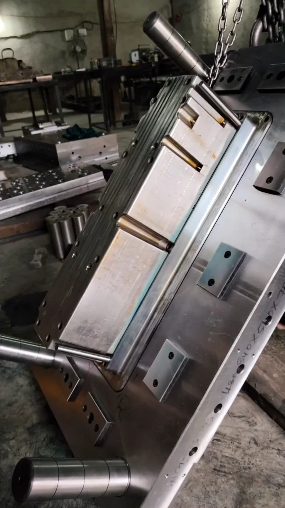
A GRP mould is a heated, hardened steel compression mould that shapes SMC (sheet moulding compound), the glass-reinforced polyester behind GRP enclosures. In this project we designed and built the GRP mould for an SMC enclosure base in our own tool room, and the first parts off the press were approved for production with no rework loop.
The brief
- An industrial SMC enclosure: a base and a lid, 46 components in the finished assembly
- A long, deep base with 3 cable entries and a side undercut
- 16 threaded inserts in the base, moulded in and located on every shot
- Target: a production-ready GRP mould that is right at the first trial
The customer name and the part dimensions stay confidential, as they do on every Prime Tools project.
Watch the full GRP mould case study
The full film runs from the brief to the approved part in about five minutes. The sections below follow it step by step.
01 · The assembly: one enclosure, 46 components
Before designing a mould we look at how the part lives in the product. The enclosure is a base and a lid, closed with screws and sealed with silicone gaskets, and every fixing lands in a threaded insert moulded into the SMC. Getting those inserts in the right place, every shot, was the core of the job.
02 · DFM review of the GRP enclosure base
Every GRP mould we build starts with a free DFM (design for manufacturing) review in 3D. For this base we checked six things before any steel was cut.
Draft analysis
The part pulls in one straight direction. The main walls carry 1° of draft per side, enough for a clean release of a deep SMC part. The few faces below 0.5° are the pin-formed bores and insert seats, which the mould forms with pins rather than the cavity walls.
Wall section
A thickness map showed most of the surface sitting in one nominal wall band, which is what SMC needs to cure evenly. Solid pillars and corner bosses were cored out to limit sink marks on the visible outer faces.
The side undercut: no slider needed
The 3 cable entries run across the pull, which would normally mean a side slider in the mould. Instead, the end wall is moulded plain with a normal split, and the 3 entries are drilled and thread-milled on our VMC after moulding, with the part held in a fixture. The result is a simpler, more robust GRP mould and accurate, repeatable threads.
Moulded-in inserts
The base carries 16 threaded inserts, 10 brass and 6 stainless steel, moulded in with no assembly afterwards. They are loaded on locating pins before each shot, their threads are sealed so no resin gets inside, and their presence is checked before the press closes. Torque and pull-out were tested on the first-trial parts.
Material, press force and charge
| Check | What we found |
|---|---|
| Material | SMC (glass-fibre thermoset), mould temperature 140–160 °C |
| Mould steel | Hardened, polished and chromed, because glass-filled SMC is abrasive |
| Moulding force needed | About 85–170 tonnes, from the projected area and SMC unit pressure |
| Trial press | 400 tonnes, with ample margin |
| Part weight | About 2.2 kg |
| Charge | Central charge covering 60–70% of the floor; flow from floor to walls to rim |
Critical features and the DFM verdict
We ranked the risks before designing the tool: the side undercut, the moulded-in inserts, flatness of the long base, sink at the solid pillars, and the sealing lip at the shear edge. Each one has a matching answer in the mould design. Verdict: geometry OK, draft OK, wall section uniform, inserts moulded in, side entries machined after moulding. Tool feasibility: go.
03 · The GRP mould: designed and built in-house
Every rib, boss and insert seat from the DFM was machined into tool steel in our own tool room in MIDC Ahilyanagar, then fitted and assembled by our team.
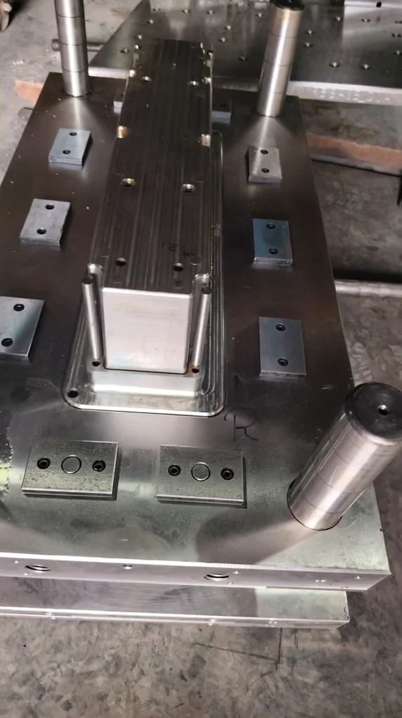
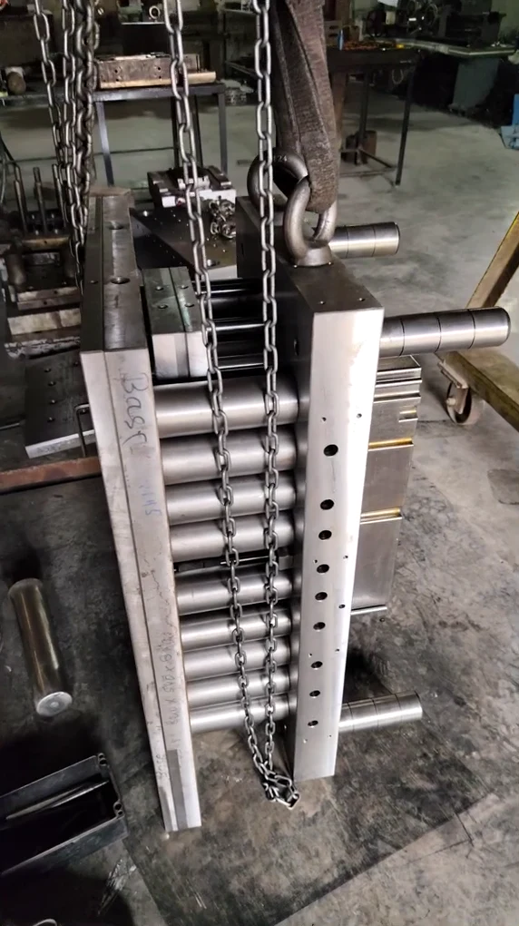
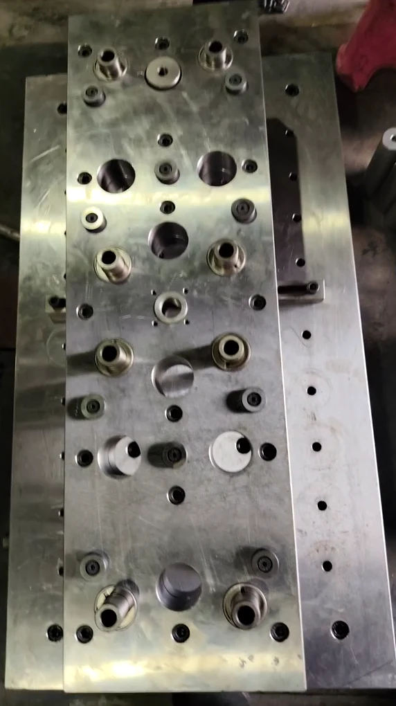
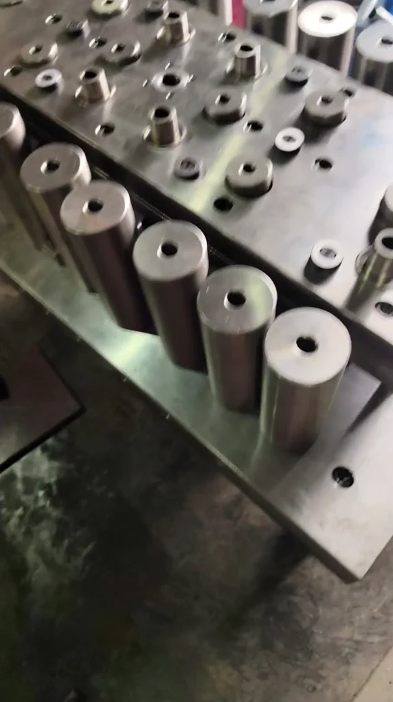
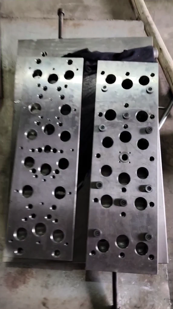
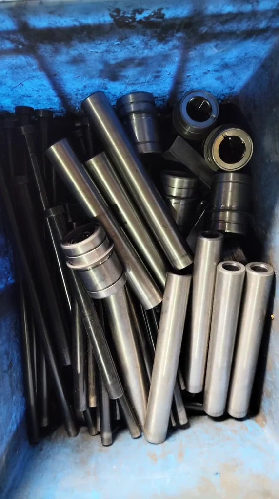
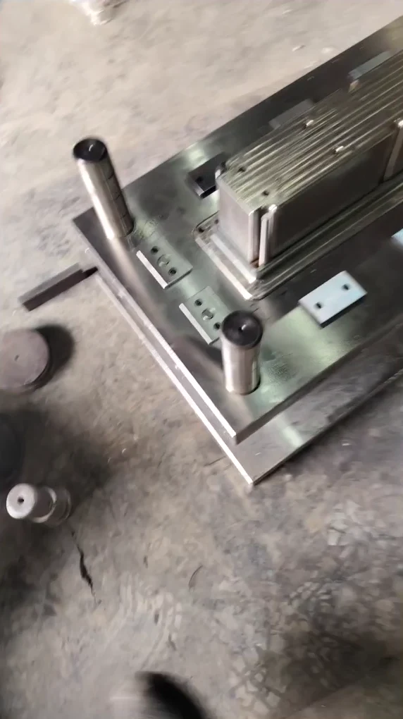
More on how we design these tools on our SMC moulds and DFM and mould design pages.
04 · Dispatch to the first trial
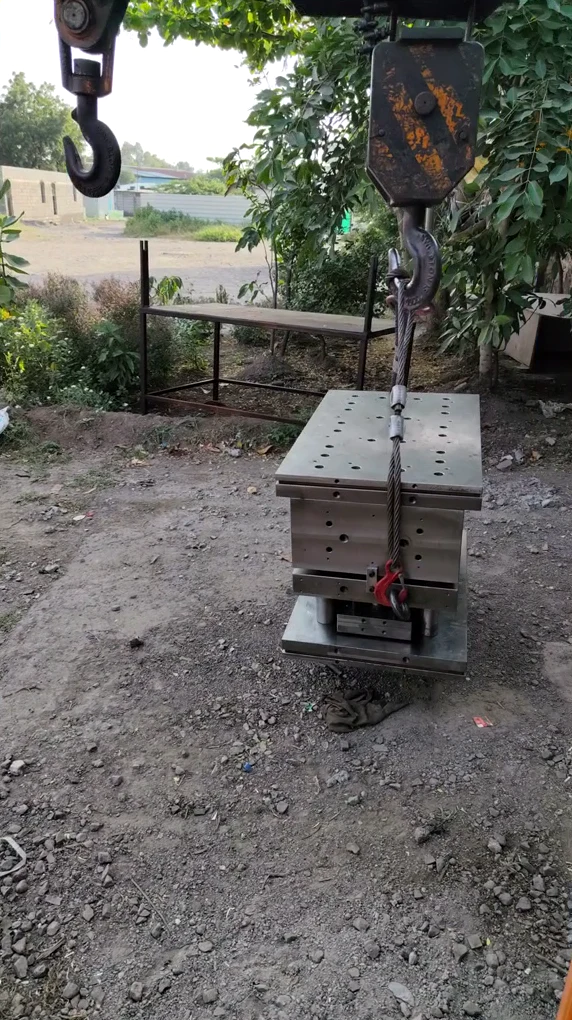
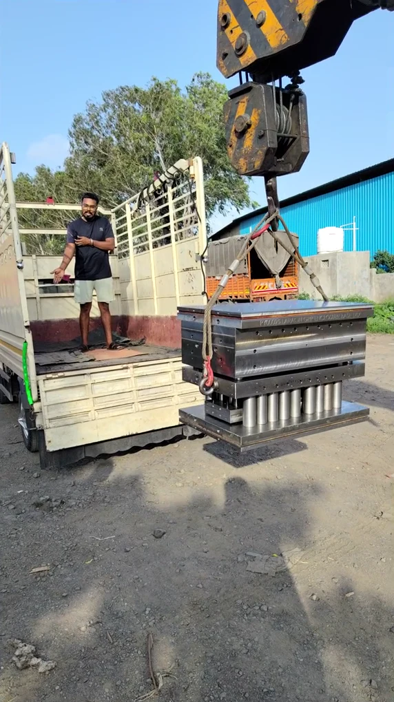
First trial: 100% OK
The mould was trialled on a 400 t press. The first parts came out with walls, ribs and insert bosses fully formed, every feature filled, and a smooth, even finish on the long outer faces. The part was signed off for production at the first trial, with no rework loop.
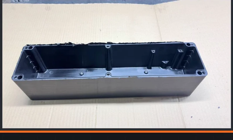
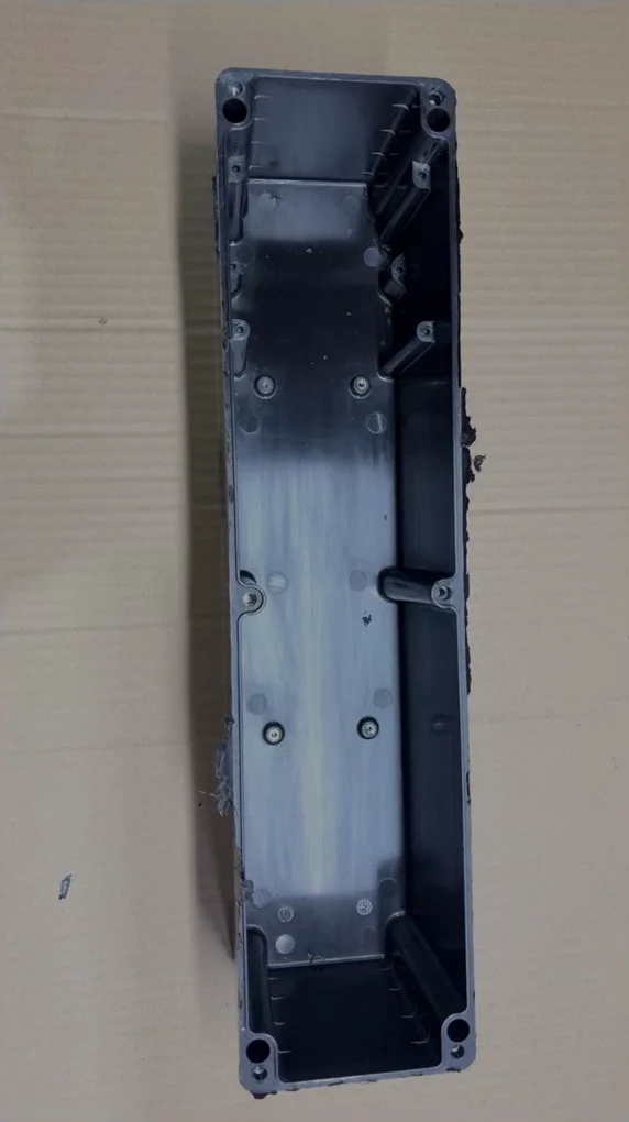
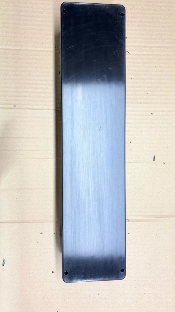
The result
100% OK at first trial
Approved for production straight away, with no rework loop.
400 t production press
Trialled on a 400 tonne press, well above the force the part needs.
46 / 32
46 components in the assembly, 32 moulded-in inserts across the set.
One team, one tool room
DFM, mould design, machining, assembly and trial under one roof.
More projects like this on our case studies page.
Need a GRP mould for your enclosure?
GRP and SMC enclosures, meter boxes, junction boxes, feeder pillars and covers all depend on the same things this project did: a DFM review before steel, the right draft and wall section, smart handling of undercuts and inserts, and a hardened, polished mould built to run. See the junction and distribution box moulds and meter box moulds we build, or our railway interior panel moulds and GRP moulds for Middle East manufacturers.
Send your part for a free DFM review
3D model or drawing, material and annual volume. We reply within one working day.