
Compression Moulding Explained: Process, Advantages and Limitations
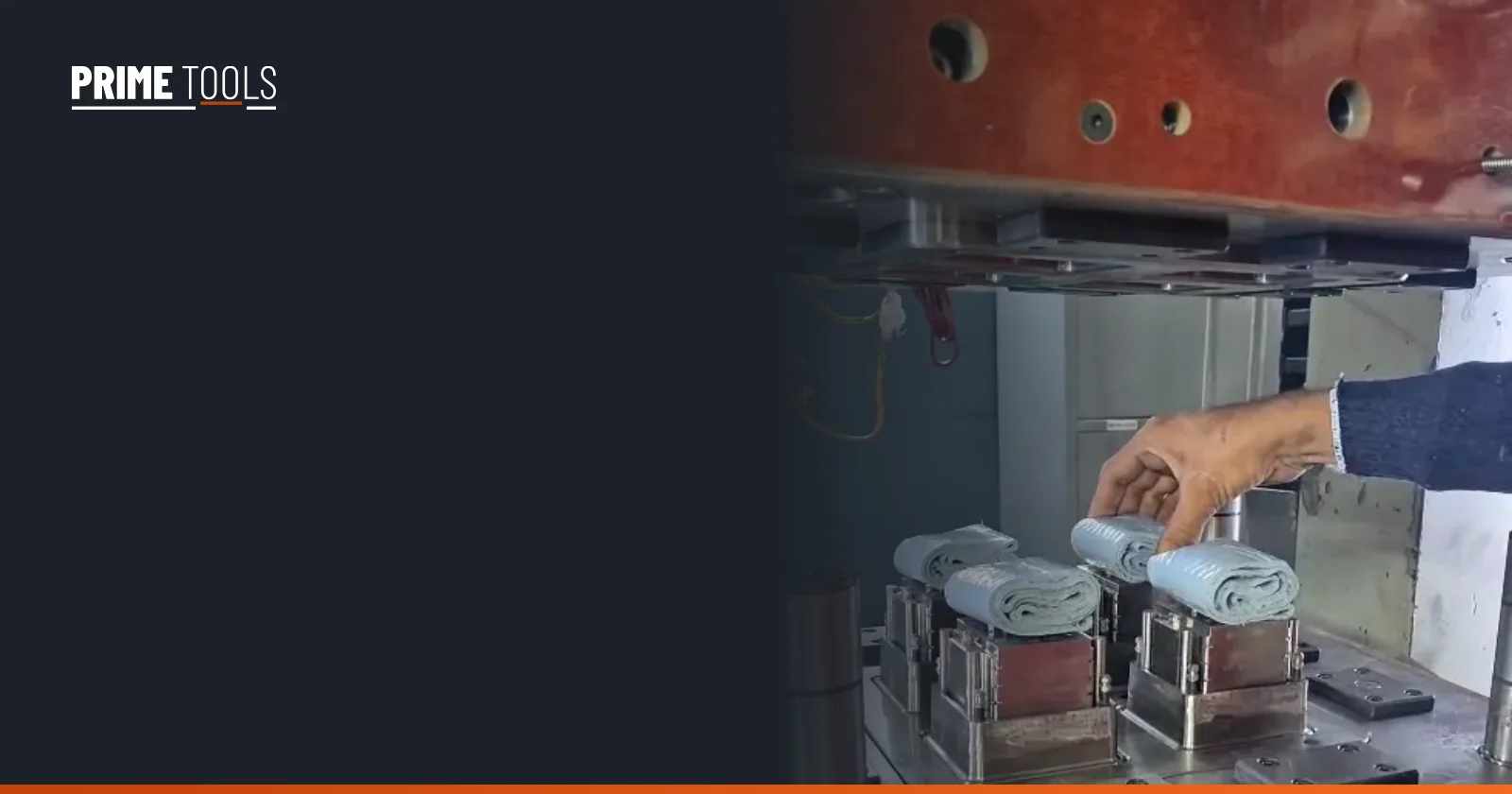
Compression moulding is a process in which a measured charge of material is placed into an open, heated mould cavity, the mould is closed in a press, and heat and pressure make the material flow to fill the cavity and then cure (or vulcanise) into the final shape. It is the main process for thermoset parts made from SMC, DMC/BMC, phenolic (Bakelite), melamine and urea-formaldehyde, and it is also used for rubber and advanced composites.
We have built compression moulds at Prime Tools since 2015. This guide explains the process the way we explain it to new customers: what happens in the mould, what the process is good at, where it struggles, and how the mould design decides whether your parts are good or full of flash.
How compression moulding works, step by step
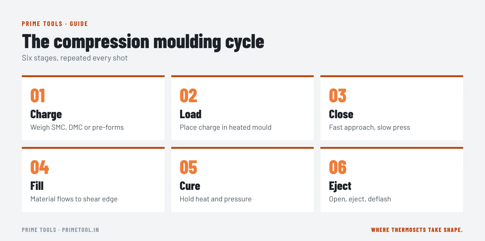
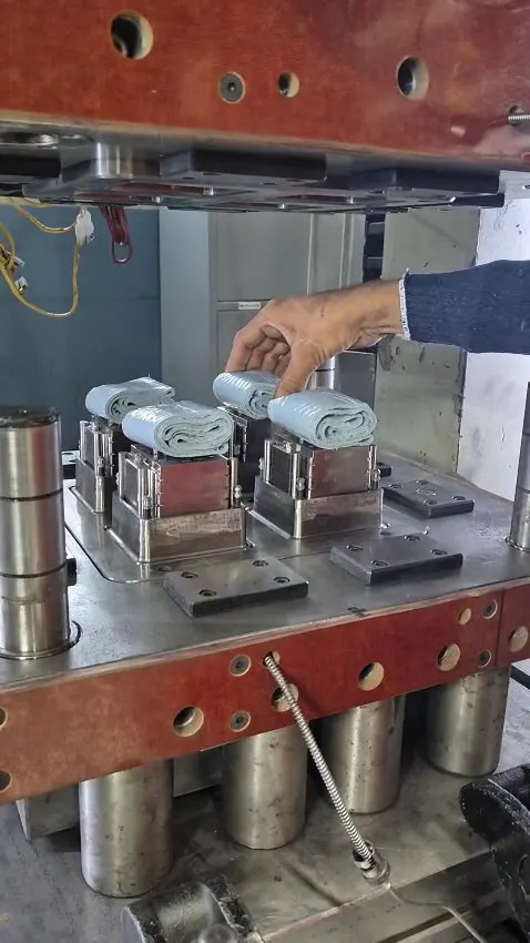
- Prepare the charge. The material is weighed. SMC is cut from sheet and stacked; DMC is cut from a log; phenolic powder may be pre-formed into tablets and pre-heated. Getting the weight right shot after shot is the first rule of good moulding.
- Load the mould. The operator (or a robot) places the charge into the lower half of the heated mould, in a position decided during design so the material flows evenly.
- Close the press. The upper half comes down. The press first closes quickly, then slows as the mould touches the material, so air can escape and fibres are not damaged.
- Flow and fill. Under pressure, the material flows outwards and fills every part of the cavity. The shear edge, a precise sliding fit between the two halves, traps the material and lets only a thin film of flash out.
- Cure. The mould is held closed while heat cures the material. For thermosets, the resin crosslinks; for rubber, it vulcanises. Thicker walls need longer cure time.
- Open and eject. The press opens and ejector pins push the part out. The part is deflashed, inspected and, if needed, post-cured or machined.
Materials used in compression moulding
- SMC (sheet moulding compound): large, strong parts such as enclosures, meter boxes, covers and panels. See SMC moulds.
- DMC / BMC: compact, detailed electrical and heat-resistant parts. See DMC and BMC moulds.
- Phenolic (Bakelite): handles, switch parts, commutators, brake components.
- Melamine and urea-formaldehyde: tableware, wiring accessories, closures.
- Rubber: seals, gaskets, grommets. See rubber vs thermoset compression moulding.
- Composites and carbon fibre prepregs: high-performance panels and parts.
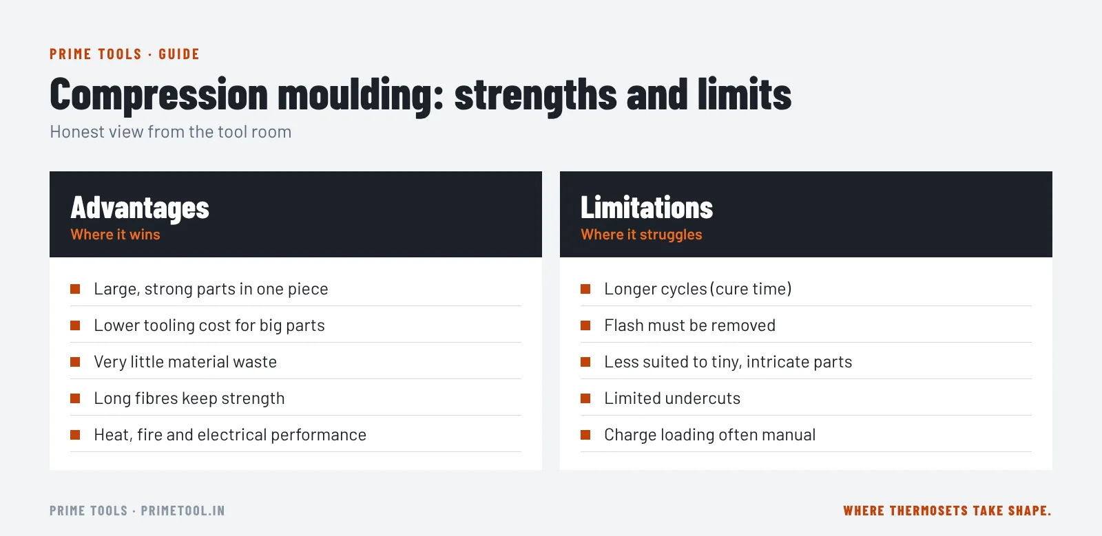
Advantages of compression moulding
- Large parts at sensible cost. Big panels and enclosures can be moulded in one piece on a press.
- Strong parts. Long fibres in SMC are not broken up by a screw or narrow gate, so parts keep high strength.
- Lower tooling cost for large parts. No runners, sprues or hot runners. A compression mould is often simpler than an injection tool of the same size.
- Little material waste. The charge is close to the part weight. There are no runners to regrind.
- Low internal stress. Short flow paths mean less fibre orientation and less warpage.
- Thermoset benefits. Heat resistance, flame performance, electrical insulation and dimensional stability.
- Good for low and medium volumes. Economical where injection tooling would not pay back.
Disadvantages and limitations
This is the section people search for most (“which is not an advantage of compression moulding”). Here are the honest limitations:
- Longer cycle times. Cure takes time, often from under a minute to several minutes depending on wall thickness, compared with seconds for many injection parts.
- Flash. A thin film forms at the shear edge and must be removed. Flash grows as the mould wears.
- Less suited to very intricate parts. Very small, complex parts with fine detail, undercuts and side actions are often better suited to transfer or injection moulding.
- Manual handling. Charge loading is often manual, so consistency depends on operator discipline unless automated.
- Limited undercuts. Side cores are possible but add cost and complexity.
- Inserts need care. Moulded-in inserts must be located well or the flow will move them.
So, a common exam answer: “high production speed for intricate parts” is not an advantage of compression moulding. Its strengths are large, strong parts with low waste and lower tooling cost.
Compression vs transfer vs injection moulding
| Compression | Transfer | Injection (thermoset) | |
|---|---|---|---|
| How material enters | Placed directly in cavity | Pushed from a pot through runners | Injected by screw through runners |
| Best part size | Medium to very large | Small to medium | Small to medium |
| Fibre length kept | Longest | Medium | Shortest |
| Tooling cost | Lowest for large parts | Medium | Highest |
| Cycle speed | Slower | Medium | Fastest |
| Inserts | Possible | Very good | Good |
| Waste | Lowest | Cull and runners | Runners |
What makes a good compression mould
Most moulding defects (flash, short fill, blisters, sticking, warpage) are mould problems or setting problems. A good compression mould gets these right:
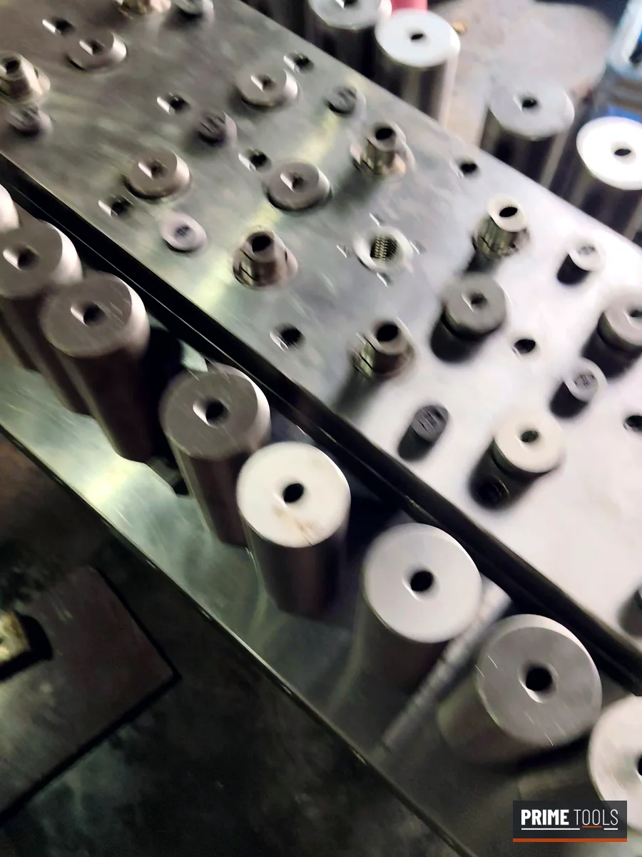
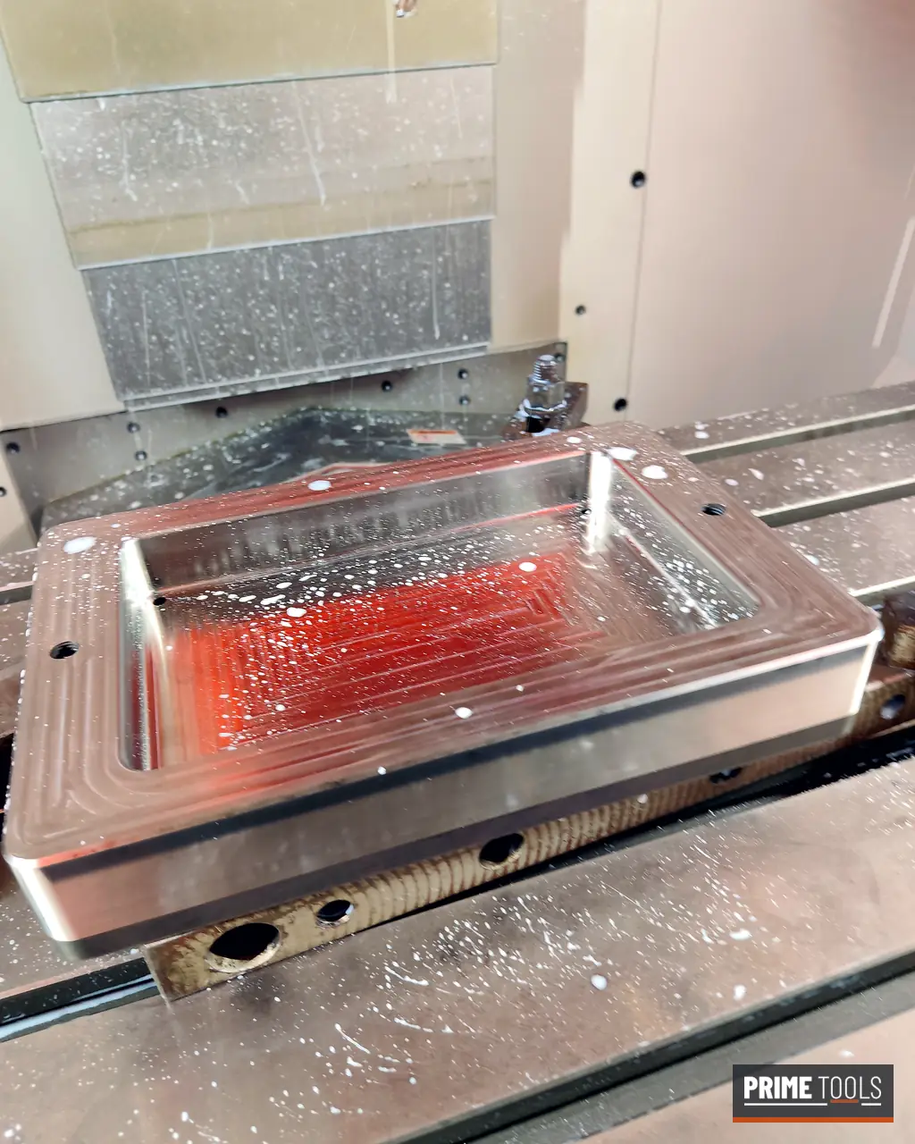
Steel and hardness. Abrasive compounds need hardened, through-hardening tool steel for cavity and core, and often surface treatment on the moulding faces.
Shear edge. The shear edge clearance decides flash thickness. It must be machined and fitted accurately, hardened, and designed so it can be reworked when it wears.
Heating. Cartridge heaters and thermocouples are placed so the whole moulding surface stays at an even temperature. Hot and cold spots cause uneven cure.
Venting and ejection. Gases from curing must escape. Ejector pins are placed for clean release without marking cosmetic faces.
Guiding and support. Guide pillars and bushes keep the halves aligned under load. Support pillars stop the plates from bending under press tonnage.
Polish. A good polish helps release and gives a better part surface. High-gloss faces are polished and, for long runs, often chrome plated.
Common compression moulding defects and causes
| Defect | Typical causes |
|---|---|
| Heavy flash | Worn or badly fitted shear edge, excess charge weight, low press tonnage |
| Short fill / non-fill | Too little charge, wrong charge placement, material pre-curing, low pressure |
| Blisters | Under-cure, trapped gases, moisture, too-thick sections |
| Sticking | Poor polish, insufficient draft, worn surfaces, release problems |
| Warpage | Uneven mould temperature, uneven wall thickness, early ejection |
| Porosity / voids | Trapped air, poor venting, closing speed too fast |
If you are seeing these on an existing mould, our mould repair team can usually diagnose it from photos and a defective part.
Free DFM review
Planning a mould for this part?
Send your 3D model or drawing, material and annual volume. Our engineers reply within one working day.
Frequently asked questions
What is compression moulding used for?
Making thermoset and rubber parts, especially large, strong ones: electrical enclosures, meter boxes, switchgear parts, manhole covers, automotive panels, seals and gaskets.
Which is not an advantage of compression moulding?
High-speed production of small, intricate parts is not a strength of compression moulding. Injection or transfer moulding usually suit those better.
What temperature is used in compression moulding?
It depends on the material. Polyester SMC and DMC usually mould with the mould around 140 to 170 °C. Always follow the material supplier’s datasheet.
What is the shear edge in a compression mould?
It is the close sliding fit between the two mould halves that traps the material and controls flash. Its fit and hardness are critical to part quality.
Is compression moulding cheaper than injection moulding?
For large parts and low to medium volumes, compression moulding usually has lower tooling cost. For small parts at very high volumes, injection is often cheaper per part.
How long does a compression mould last?
With hardened steel and regular maintenance, a compression mould can run for many years and very large numbers of shots. Shear edges and surfaces need periodic rework.

Written by the Prime Tools engineering team
Compression mould makers in MIDC Ahilyanagar, Maharashtra, since 2015. We design and build moulds for SMC, DMC/BMC, Bakelite, melamine and urea parts, and repair die casting dies. About us
Keep reading
Processes
Choosing a Compression Moulding Press: Tonnage, Platen Size, Daylight and More
What to check when choosing a compression moulding press: tonnage, platen size, daylight, speed control, ejection and heating, and how it must match the…
5 min read · Read article →
Processes
Compression Moulding of Rubber vs Thermosets vs Composites and Carbon Fibre
How compression moulding differs for rubber, thermosets (SMC, DMC, Bakelite) and composites: materials, temperatures and mould design.
5 min read · Read article →
Processes
How the Sheet Moulding Compound (SMC) Process Works, Step by Step
The sheet moulding compound (SMC) process from paste mixing and sheet making to maturation, charge cutting, moulding and finishing, with tooling tips.
6 min read · Read article →